SIMPLIFIED DESCRIPTION OF PL510 TACH WIRING
This discussion only applies to the "inductively coupled" stock tachometer.
Many later models use a "directly coupled" tachometer. I can't provide any
information about those since I've never owned or worked with one.
There is an existing light and power sub-harness that connects two lights to
this segment of the instrument panel and provides power to the factory clock (or
tachometer when installed). The GREEN and BLACK extensions may be used as the
necessary
connections for your new tach power and ground.
NOTE:
The BLUE wire is not switched by design. It provides fulltime +12V to the
clock and to the tachometer when connected using this sub-harness. I
personally prefer to use a switched +12V source to power my tach.
|
GREEN WIRE - WHITE STRIPE
|
+12V switched from LIGHTS switch.
|
|
BLUE WIRE
|
+12V, live from Fuse Box.
|
|
BLACK WIRE
|
Ground.
|
The three-pin connector connects to the shape matching, three-pin
Tachometer/Clock Connector on the main
harness.
|
GREEN WIRE - WHITE STRIPE
|
+12V switched from LIGHTS switch.
|
|
BLUE w/WHITE STRIPE
|
+12V, live from Fuse Box.
|
|
BLACK WIRE
|
Ground.
|
NOTE:
This existing wiring should work perfectly. But on my 72 PL510 two different
tachs would not work until I installed a dedicated ground and +12V source.
Fortunately, there are several convenient locations for a dedicated ground and
the
switched +12V source
for the radio has an open bullet connector within inches of the instrument
panel location. I used it instead and everything worked perfectly.
Later I found a break in the BLUE w/WHITE STRIPE wire that had caused the
failure. Since I preferred a switched +12V source, I just left it the way I
had gotten it working.
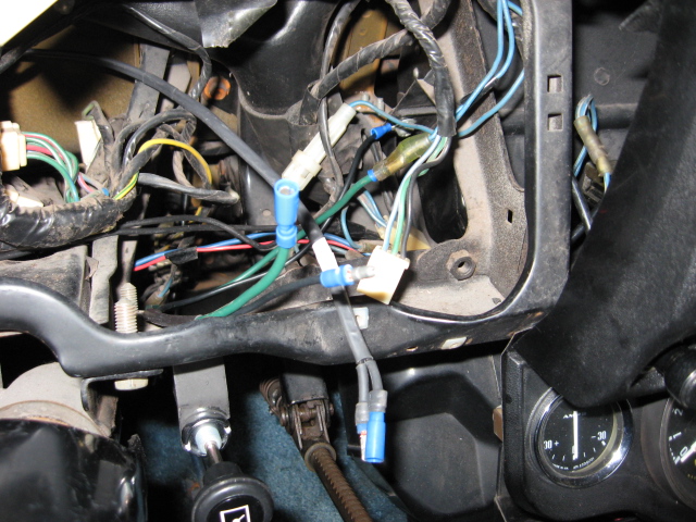
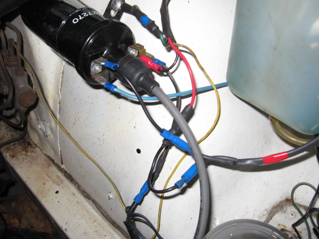
In the picture above you can see;
-
the three-pin Tach/Clock Harness Connector with the GREEN, BLUE w/WHITE
STRIPE, and BLACK wires
-
the small harness (GREEN and BLACK wires) I built to connect the switched
+12V female double-bullet connector (normally used for the radio power source)
and a chassis ground
-
the harness I built to connect the tachometer to the coil area in the engine
compartment (black with a white tape marker on it). It connects to the male
and female bullet connectors on the tachs's WHITE wire. Be sure to read the
"Inductive Coupling Loop"
discussion further down the page.
The tachometer has the following circuits:
|
GREEN WIRE
|
Goes to the middle of the tach.
+12V from the Ignition Switch, ACC or ON.
|
|
BLACK WIRE
|
Goes to the middle of the tach. Ground for tachometer.
|
|
LOOPED WHITE WIRE
|
Inductive coupling loop. See below.
|
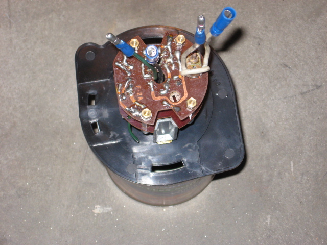
You should also notice in the above picture of the back of the tach that there
is a small potentiometer (about 5:30 o'clock). This provides some calibration
adjustment.
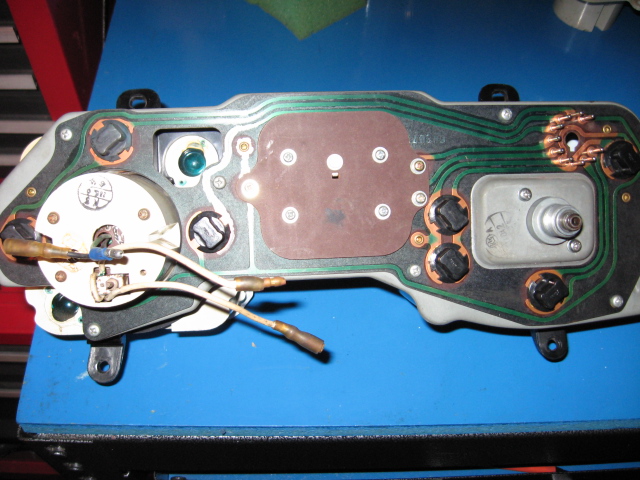
Rear view of the 70-73 PL510 Intrument panel with tachometer
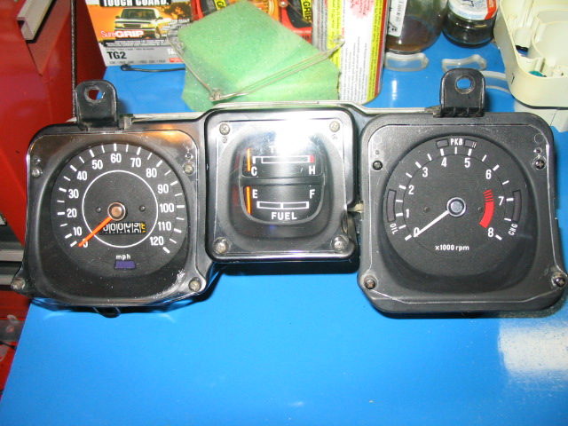
Front view of the 70-73 PL510 Instrument panel with tachometer
Inductive Coupling Loop
You will need to extend both ends of the white wire out to the coil area in the
engine compartment.
-
On a stock ignition system (points distributor and external ballast resistor),
the LOOPED WHITE WIRE should be wired in series between the +12V from the
Ignition Switch and the Ballast Resistor.
-
If you are using a later model "matchbox" distributor and an internal resistor
coil, you may need to try both of the following choices to see which gives the
best results;
-
Connect the LOOPED WHITE WIRE in series between the +12V wire from the Ignition
Switch and the Positive (+) post on the coil.
-
Connect the LOOPED WHITE WIRE in series between the Negative (-) post on the
coil and the "C" post on the matchbox module.
CONFIRMATION:
This method worked properly on a 1972 PL510
CONFIRMATION:
This method worked on a 1973 240Z. The stock Z tach uses the exact same wiring
as the 510 tach.
Polarity makes a difference here
. So if it doesn't operate the way you have it
wired in series, try switching the leads.
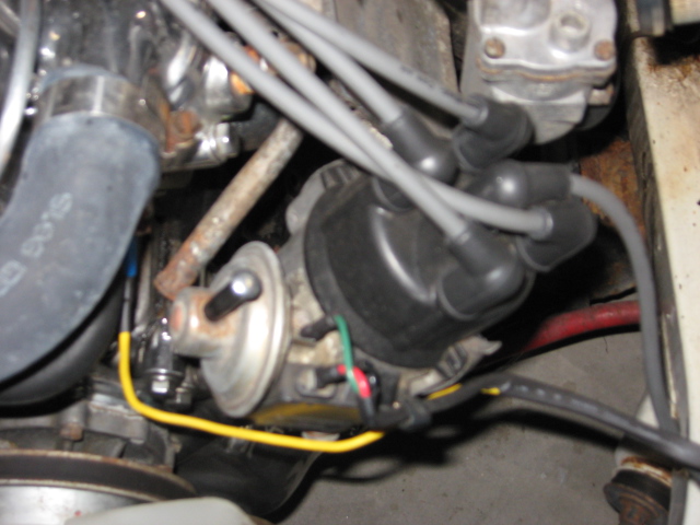
 Here you see the coil area in the engine compartment. This is an internal resistor coil in use with a Matchbox distributor. The following wiring discussion applies to that type of setup.
The 2 wire harness that extends the tachometer's LOOPED WHITE WIRE to the coil are can be seen (black with a red tape marker). The right side of the coil is the positive (+) side.
NOTE: There are some "unnecessary" connectors in use here... so I can easily exclude the tachometer from the circuit... and I didn't match the colors. I really should have used RED wire.
Here are the coil connections:
- The BLACK w/YELLOW STRIPE wire connects to the (+) post on the coil and is the +12V source from the Ignition Switch via the engine compartment harness.
- The BLACK wire connects to the (+) post on the coil and runs through a 4 wire harness to the distributor and connects to the "B" post on the Matchbox module.
- The RED wire connects to the (-) post on the coil and runs thorough a 4 wire harness to the distributor and connects to the "C" post on the Matchbox module.
Connecting the inductively coupled tachometer: Wire the tachometer's LOOPED WHITE WIRE in series with the negative (-) side of the ignition circuit.
- Disconnect the RED wire from the (-) post of the coil. Then reconnect the RED wire to one leg of the LOOPED WHITE WIRE extension harness.
- Connect the other leg of the LOOPED WHITE WIRE extension harness to the (-) post on the coil.
- Reread the hint about "Polarity" above.
- The GREEN wire connects to a chassis ground at the coil mount and runs through the 4 wire harness and connects to the "A" post on the Matchbox module.
- The YELLOW wire connects the Temperature Sensor to the YELLOW wire in the engine compartment harness.
NOTE: You may notice a BLUE wire connected to the (-) post of the coil. This allows me to connect a "directly coupled" tachometer while I'm testing the calibration of the "inductively coupled" stock tach.
 Here is a shot of the Matchbox module connections just to help you complete the visual picture.
References:
Datsun Technical Bulletin - Procedure for tachometer installation - 510 series vehicles
Riley Curtis' notes on his 73 240Z