![]()
SU Type Twin Carburetor
![]()
|
|
|
INTRODUCTION TO THIS WEB PAGEThis web page on the Hitachi-SU carburetor is copied from a Service Manual for the Datsun 510, published by Nissan, whose permission to copy we gratefully acknowledge. We used optical character recognition to avoid huge graphics files with their inherent slowness on the net; naturally we then went over the data with a fine tooth comb on a best effort basis but we do not warrant that the data are 100% identical to the original. If any of you detect an error please let Pat know at pmullen@direct.ca. Thanks. We also added some data for the Datsun Roadsters to the "Specifications". The SUs fitted to most Roadsters are quite similar to those dealt with in this article. We prefered to copy this article, rather than one from any of the Roadster shop manuals, because it considers points, such as the needle valve problem dealt with below, not covered in the earlier Roadster manuals. We find that the standard web display resolution of 800x600 is best. We have tried to ensure that you can print the entire web page (about twenty 8 1/2" x 11" pages) without having graphics split onto two pages. It works better with Netscape 3 and 4 than with Netscape 2; it's best to specify 0.25" margins. Important notice regarding tuningBefore you retune your SU - any SU on any engine - please be aware that one of the most common ways to burn out the exhaust valves on an engine fitted with one or more SUs is to lean out the mixture because you were unaware that the needle valve in the float chamber was leaking when you tuned the SU. WHY IT HAPPENS When the engine is idling the fuel pump is producing enough pressure to overcome the resistance of an old tired needle valve in the float chamber, and so the carburetor floods. As you tune an SU at idle, this means that you temporarily have a rich mixture which can fool you into believing that you should turn the mixture adjusting nuts (called "idle adjusting nuts" in the Nissan article) so as to lean out the mixture. Don't do it! Read below. HOW TO AVOID THIS DISASTER Instead, do as the table in Idling adjustment advises (in regards to setting the idle speed) and "race the engine" (they mean take it up to about 3-4000 rpm for ten seconds) and then shut the engine down to idle and immediately judge whether the nuts need adjusting; this is best done by using the piston lifter (not mentioned in the Nissan article, but clearly seen in External view of carburetors - one is slightly below the right of the air intake on the RH carb directly above the "al" of "external" - to lift the piston about 1/32" - if the carburetor is adjusted properly the engine speed should momentarily increase very slightly and then return to what it was before you lifted the piston. If you find the the mixture is no longer as rich - you have one or more leaky needle valves. If they are leaking, buy a new needle valve for each float chamber and try again; as a temporary measure you can try to lap the old valve to its seat or, as a last resort, simply follow the advice in the paragraph above. In any case, even with perfect needle valves, you should always make your decision (as to whether or not to adjust the nuts) immediately after revving the engine, closing the throttle and lifting the piston as described above.
DESCRIPTION |
|
The model HJL38W6 carburetor is of a
horizontal, variable venturi type, which is used in the L16 and L18
engines. This carburetor is designed to keep constant flow of intake air
through the venturi under all engine speeds. That is, the venturi
opening is automatically adjusted by sliding the suction piston in
accordance with the change in volume of intake air.
Metering calibration is accomplished entirely by the jet needle fixed into the suction piston. Then, the relative position of the taper jet needle and nozzle gives the correct air-fuel mixture covering all operating speeds. |
|
|
|
When starting the engine, the nozzle is
lowered by pulling the choke knob. Consequently, an enriched air-fuel
mixture is obtained. Under normal running, the vacuum in the suction
chamber lifts the suction piston which slides the jet needle up and the
proper mixture is supplied.
This carburetor has the following characteristics: |
1. Air flows fast in the venturi when the
engine runs at low speeds. Therefore, fuel is fully turned into spray,
so that good driveability can be obtained.
2. As the venturi opens wide at high speed running, high output can be provided to reduce fuel intake resistance. 3. The fuel control mechanism is simple in construction because of single nozzle, |
thus affording troublefree operation and
smoother acceleration.
4. Engine output and accelerating characteristics are greatly improved by the use of two parallel synchronized carburetors. This means that the fuel is fed to two engine cylinders by the front and rear carburetors evenly. |
|
1 Suction chamber
2 Suction spring 3 Float chamber cover 4 Suction guide 5 Nipple 6 Throttle chamber 7 Suction piston rod 8 Needle valve 9 Throttle valve 10 Float chamber 11 Float lever 12 Float 13 Sleeve 14 Clip 15 Fuel hose 16 Oil cap nut 17 Plunger rod 18 Transverse hole 19 Oil damper 20 Suction piston 21 Nozzle 22 Idle adjusting nut |
|
|
![]()
![]()
![]()
![]()
|
||
| The procedure for idling adjustment is described herein since proper idling adjustment of these two carburetors is extremely important in obtaining peak vehicle performance and in effectively |
reducing fuel consumption.
It should also be noted that improper carburetor adjustment has an adverse affect not only upon idling but also upon |
acceleration, output, fuel consumption, and other vehicle performance factors. |
![]()
|
![]()
| Operating procedure | Instructions |
| 1. Remove air cleaner. | a. Warm up engine prior to adjustment, and fully return choke lever. |
| 2. Loosen both front and rear carburetor throttle adjusting screws, balance screw, and fast idling setting screw. | a. Make sure front and rear throttle shafts are not connected. |
|
3. Tighten front and rear idle adjusting nuts all the way, and turn
out as required according to outside temperatures and altitude. Refer to
Figures EF-41 and 42..
Note: Always turn in or out these nuts equally. |
a. Determine best idling mixture by referring to Figures EF-41 and 42.
b. Also refer to Figures EF-41 and 42, for altitude at which vehicle is to be operated. |
| 4. Turn in front and rear throttle adjusting screws a few turns, and start engine. | a. Make sure that the engine is at normal operating temperature. |
| 5. Turn in or out front and rear throttle adjusting screws and reduce the engine speed to 600 to 700 rpm. | a. Reduce engine speed to the extent that the engine operates stably. |
| 6. Apply a flow meter to front carburetor air cleaner flange, turn in or out air flow adjusting screw, and align the upper end of the float in the glass tube to the scale. | a. Stand the flow meter float vertically. |
| 7. Then apply the flow meter to rear carburetor air cleaner flange. (Do not move the flow meter air flow adjusting screw.) If the flow meter float is not aligned with the front carburetor scale, turn in or out rear carburetor throttle adjusting screw and align float with the front carburetor scale. |
a. Match front and rear throttle valve openings.
b. Throttle valve openings are even, and air flow is also uniform when the positions of the floats in the glass tubes of the flow meters stop at the same position for both front and rear carburetors. |
| 8. Turn in or out front and rear idle adjusting nuts simultaneously by each 1/8 turn until the fastest and most stable engine speed is obtained. |
a. Idling fuel flow quantity is reduced by tightening idle adjusting
nut (turning it to the right) and is increased by loosening idle
adjusting nut (turning it to the left).
b. Front and rear idle adjusting nut adjusting positions (number of turns by which both nuts are backed off) must be the same. |
| 9. Back off (loosen) front and rear throttle adjusting screws, and set engine speed to rated speed. |
a. Repeat steps 6 and 7 above, and set engine speed to rated speed by
adjusting front and rear carburetors so that the air flow of both front
and rear carburetors is the same. Rated idling speeds of the L16 and L18
are as follows:
Engine idle speed rpm: 650 Standard vacuum at idle speed, mmHg/(inHg): 400(15.75) or above |
| 10. Turn in balance screw until screw head contacts the throttle connecting lever. |
a. Make sure that idling speed does not change.
b. Adjust balance screw so that suction pistons act simultaneously. |
| 11. Move throttle shaft, and rapidly accelerate the engine (race the engine) a few times. Make sure that idling speed does not change. | a. Make sure that adjustment is proper. |
|
12. Turn fast idle setting screw to increase engine speed
approximately 1,500 rpm., apply the flow meter to both front and rear
carburetors, and verify that the flow meter float positions are even.
If uneven, readjust balance screw. |
a. Increase engine speed, and insure that the link interlock action
operates properly.
b. Readjust balance screw and match the air flow of front and rear carburetors. |
| 13. Back off fast idle setting screw and decrease engine speed. After racing engine, apply the flow meter to front and rear carburetors, and re-confirm that the float positions are even. If uneven, adjust front and rear throttle adjusting screws so that engine speed does not change, and equalize the flow meter float positions. Then, repeat step 12. |
a. Match the idling air flow of front and rear carburetors.
b. Adjust idling speed. |
| 14. Set throttle shaft so that throttle valve starts to open, and adjust the clearance at fast idling setting screw to 1 to 2 mm (0.0394 to 0.0787 in). |
------------ |
| 15. Stop engine, and install air cleaner and duct. |
------------ |
|
![]()
![]()
![]()
![]()
![]()
![]()
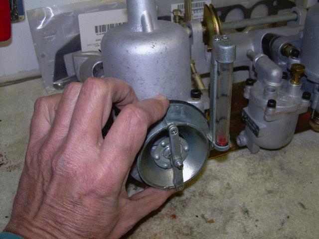
| Carburetor should not be disassembled unless absolutely necessary. When it must be disassembled, extra caution should be exercised to avoid damaging venturi and other components which consist of very high precision parts. |
![]()
![]()
![]()
|
2. Assembly
(1)For centering piston and suction chamber, remove oil cap nut with parts properly assembled (jet needle and suction piston assembled) without damper oil applied. (2) Assemble nozzle sleeve, washer, nozzle sleeve set screw by tightening nozzle sleeve set screw temporarily. (3) Set suction piston to its fully closed position, and insert nozzle until it contacts nozzle sleeve. (4) When nozzle jet contacts with jet needle, move nozzle sleeve slightly so that it is at right angle to center axis, |
and position nozzle Sleeve so that nozzle jet
does not contact with jet needle.
(5) Without disturbing the above setting, raise suction piston with your finger, and lower it slowly. If suction piston drops smoothly until suction Piston stop pin drops on venturi, making a light striking sound, the condition of piston is satisfactory. Securely tighten nozzle sleeve at this position with nozzle sleeve set screw. (6) Remove nozzle, install idle adjusting, spring, and idle adjusting nut on nozzle sleeve, and reinstall nozzle. Connect fuel line leading to float chamber to nozzle nipple, and tighten |
clip fully.
Note: Exercise care not to twist fuel line. (7) With choke lever lightly pulled out, place connecting plate between 4 mm (0.1575 in) washer and sleeve collar 4 mm (0.1575 in); fasten plate to nozzle head by means of screws, 4 mm (0.1575 in). In installing plate, check to be certain that collar is installed in hole in plate by moving choke lever as necessary. (8) After the above steps have been completed, again check to be sure that suction piston lowers freely without binding. |
![]()
Disassembly of float chamberTo disassemble, follow steps given under "CONTROL AND ADJUSTMENT - Adjustment of float level". |
![]()
![]()
|
Item |
Carburetor Model |
||
|
I |
HJL38W6 |
HJB38W |
HJG46W |
| Applied engine (car) | L16 & L18 (510) | R (SPL311-1600) | U20 (SRL311-2000) |
| Bore, mm (in) | 38 (1.4961) | 38 (1.4961) | 46 (1.8111) |
| Piston lift, mm (in) | 29 (1.1417) | ||
| Jet needle | M-76 | ||
| Nozzle jet dia., mm (in) | 2.34 dia. (0.092 1) | ||
| Suction spring | #23 | ||
| Float chamber needle valve, inner dia., mm (in) | 1.5 dia. (0.059 1) | ||
| Float level, mm (in) | 23 (0.9055) | ||
| Float venting | Inner vent type | ||
| Fuel pressure, kg/sq cm (lb/sq in) | 0.24 (3.4140) | ||
| Throttle clearance at full throttle, mm (in) | 0.6 (0.0236) | ||
| Position at full throttle | 6.5 degrees | ||
![]()
| The causes of trouble and appropriate corrective actions are shown on TABLE to permit immediate repair of carburetor in the event carburetor trouble develops. | Improper engine operation can be attributed to many different causes. Although carburetor may be normal, if the electrical system is defective, the cause of trouble sometimes may seem to be in carburetor. If engine does not operate satisfactorily, first check electrical system before attempting to adjust carburetor. |
|
Condition |
Probable cause |
Corrective action |
| Overflow | Leakage from float, or float bent or damaged. | Replace float. |
| Dirty needle valve seat. | Clean valve seat. | |
| Loose needle valve. | Retighten. | |
| Defective needle valve seat. | Refit or replace. | |
| Excessive fuel pump pressure. | Repair pump. | |
| Fuel pump drawing in air. | Repair pump. | |
| Excessive fuel consumption | Overflow. | Described above. |
| Faulty suction piston operation. | Described below. | |
| Defective nozzle return. | Readjust. | |
| Worn jet needle. | Replace. | |
| Worn nozzle jet. | Replace. | |
| Improper idling adjustment. | Readjust. | |
| Jet needle not properly installed. | Readjust. | |
| Improper throttle valve interlock adjustment. | Readjust. | |
| Insufficient output | Throttle valve does not open fully. | Readjust. |
| Faulty suction piston operation. | Described below. | |
| Defective nozzle return. | Readjust. | |
| Nozzle or fuel line clogged. | Clean. | |
| Jet needle not properly installed. | Readjust. | |
| Needle valve clogged. | Clean. | |
| Defective fuel pump. | Readjust. | |
| Improper idling | Faulty suction piston operation. | Described below. |
| Defective nozzle return. | Readjust. | |
| Worn jet needle. | Replace. | |
| Improper idle adjusting nut adjustment. | Readjust. | |
| Worn throttle valve shaft. | Replace. | |
| Air leakage due to defective packing between manifold and carburetor. | Replace gasket. | |
| Improper throttle valve interlock adjustment. | Readjust. | |
| Loose throttle lever interlock link. | Readjust or repair. | |
| Engine operation is irregular or erratic | Defective suction piston. | Described below. |
| Insufficient damper oil or improper oil used. | Replenish or replace. | |
| Improper idling adjustment. | Readjust. | |
| Jet needle not properly installed. | Readjust. | |
| Engine does not start. | Overflow. | Described above. |
| No fuel fed to the engine. | Check pump, fuel line. and needle valve. | |
| Improper idling adjustment. | Readjust. | |
| Defective suction piston. | Described below. | |
| Faulty suction piston operation | Sticking due to dirt and other foreign matter. | Clean. |
| Sticking due to deformation (bulging or caving) of suction chamber or suction piston. | Repair or replace. | |
| Nozzle not properly centered. | Correct. | |
| Bent jet needle. | Replace. | |
| Bent plunger rod. | Correct. |
![]()
 oil cap nut, be careful not to
bend rod. If oil cap nut is loose, it may fall off. Be sure that it is
sufficiently tightened by hand.
oil cap nut, be careful not to
bend rod. If oil cap nut is loose, it may fall off. Be sure that it is
sufficiently tightened by hand.
 shoulder portion is flush with
the bottom of suction piston. Apply an appropriate tool having a
horizontal (flat) surface such as slide calipers to the lower end as
shown in Figure EF-51, so that the shoulder of jet needle contacts the
surface of tool, and tighten jet needle set screw. Jet needle will then
be installed correctly.
shoulder portion is flush with
the bottom of suction piston. Apply an appropriate tool having a
horizontal (flat) surface such as slide calipers to the lower end as
shown in Figure EF-51, so that the shoulder of jet needle contacts the
surface of tool, and tighten jet needle set screw. Jet needle will then
be installed correctly.
 oil, etc. from piston and
chamber.
oil, etc. from piston and
chamber.